 GridEon
Docs / General
Cables and wiring
GridEon reads equipment over RS485: two wires, A (+) and B (−), from the inverter's or battery's communication port to a USB–RS485 adapter plugged into the device.
The inverter
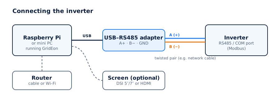
- Plug the USB–RS485 adapter into a USB port on the device.
- Connect A on the inverter to A (+) on the adapter and B to B (−). Use one twisted pair of the cable for A and B.
- If both the adapter and the port have GND, connect it too (a third wire), especially over long distances.
Inverter and battery
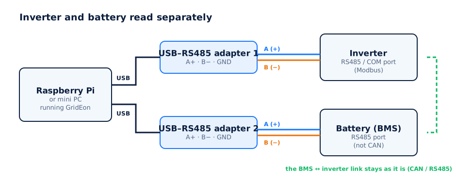
The battery is read straight from the BMS on a second adapter. The link between the BMS and the inverter (usually CAN or RS485) stays exactly as it is: GridEon doesn't touch it.
The RJ45 plug
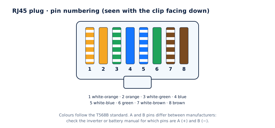
Many inverters and batteries have their communication port as an RJ45 socket. The manual tells you which pins are A and B (for example "pin 1 = B, pin 2 = A"). Cut a network cable, keep the plug for the equipment side and connect the matching wires to the adapter.
WarningDon't connect the adapter to the inverter's CAN or “BMS” port, or to Ethernet sockets. Use the RS485 / COM monitoring port given in the manual.
Tips
- Doesn't work at first? Swap A and B. This is the most common cause.
- For distances over 10 m, use shielded cable (FTP) and connect GND.
- Keep the data cable away from power cables (AC, PV, battery).
- Several devices on the same adapter (one RS485 line) only work with different Modbus addresses. Simple and safe: one adapter per device.